ATtiny88初体验(二):呼吸灯
前面的“点灯”实验实现了间隔点亮/熄灭LED,但是间隔时间和亮度都没法控制,为了解决这个问题,可以使用ATtiny88的定时器模块。
ATtiny88单片机含有2个定时器,定时器0是8bit的,定时器1是16bit的,其中定时器1支持PWM功能。查询手册得知,定时器1的两个通道的输出脚为PB1和PB2,而MH-ET LIVE Tiny88核心板的LED连接的是PD0脚,因此无法利用定时器1的PWM功能控制板载LED。这里介绍基于定时器0,通过软件模拟PWM控制板载LED的方法。
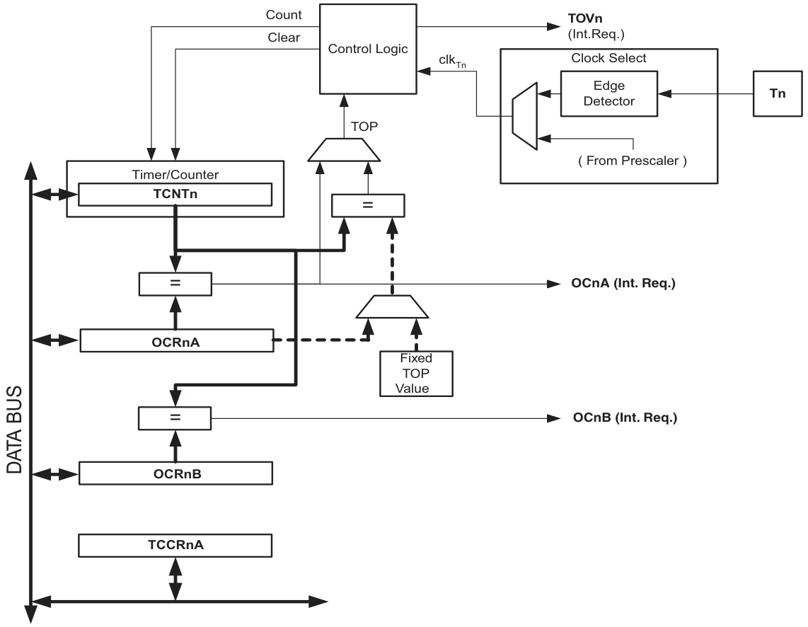
定时器0介绍
ATtiny88的定时器0是一个8bit的定时器,拥有两个独立的输出比较单元,支持CTC模式,拥有三个独立的中断源(TOV0,OCF0A,OCF0B)。
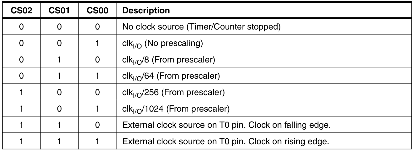
定时器0的时钟源可以是由内部时钟源分频而来,也可以是来自T0(PD4)引脚的外部时钟源。
注意:在使用定时器0时,务必确保 PRR 寄存器中的 PRTIM0 位值为0。
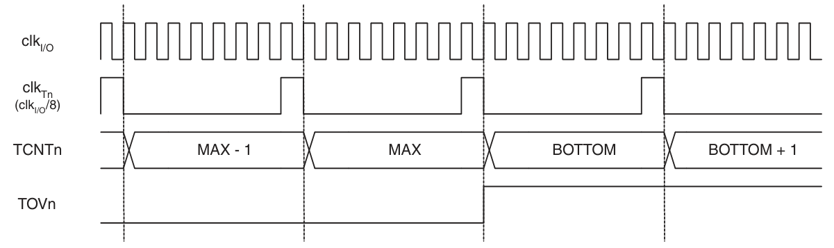
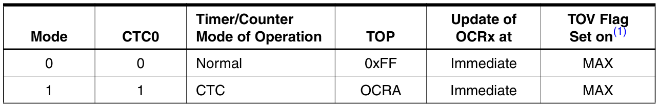
普通模式
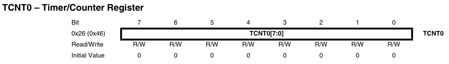
在普通模式下, TCNT0 寄存器的值从0x00一直增加到0xFF,然后回到0x00,如此往复。当 TCNT0 寄存器的值回到0x00时, TOV0 标志位置位,同时触发 TIMER0_OVF 中断。
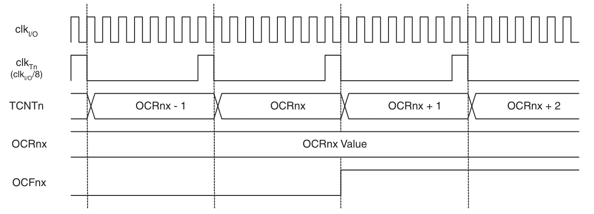
当 TCNT0 寄存器的值与 OCR0x 寄存器的值相等时, OCF0x 标志位将在下一个时钟置位,同时触发 TIMER0_COMPx 中断。
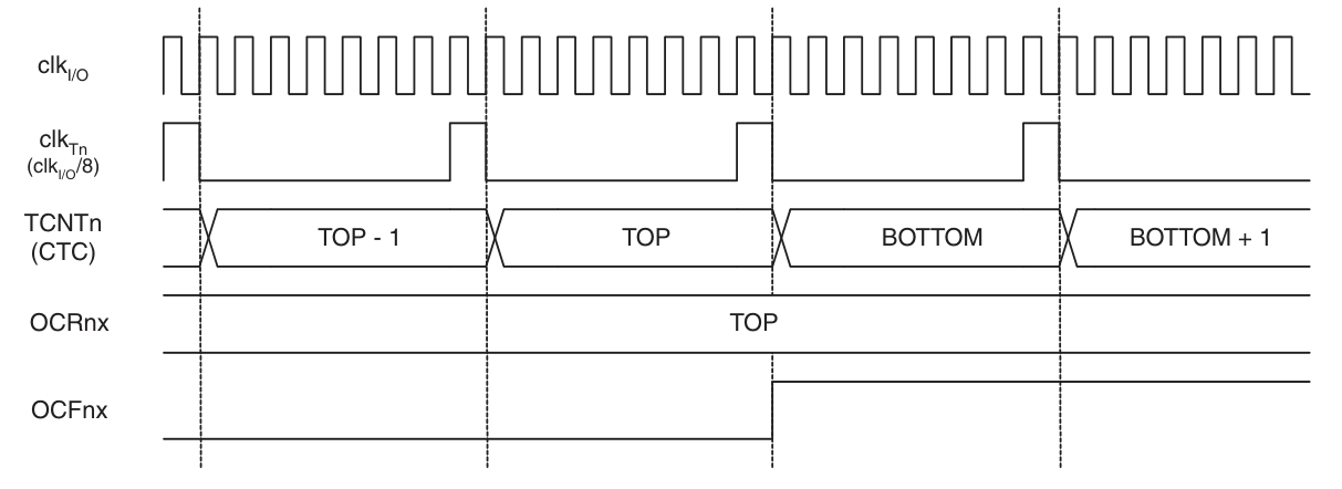
CTC模式
在CTC(Clear Timer on Compare Match)模式下, TCNT0 寄存器的值从0x00一直增加到和 OCR0A 寄存器相等,然后回归到0x00。当 TCNT0 寄存器的值回到0x00时, OCF0A 标志位置位,同时触发 TIMER0_COMPA 中断。
寄存器
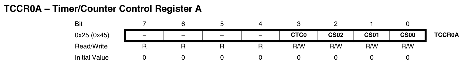
CTC0 :CTC模式, 0 为普通模式, 1 为CTC模式。
CS0[2:0] :时钟源选择。
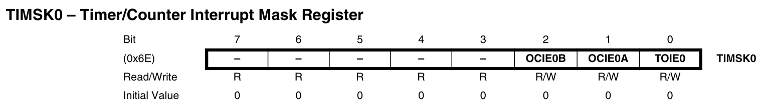
OCIE0B :置 1 时使能 TIMER0_COMPB 中断。OCIE0A :置 1 时使能 TIEMR0_COMPA 中断。TOIE0 :置 1 时使能 TIMER0_OVF 中断。
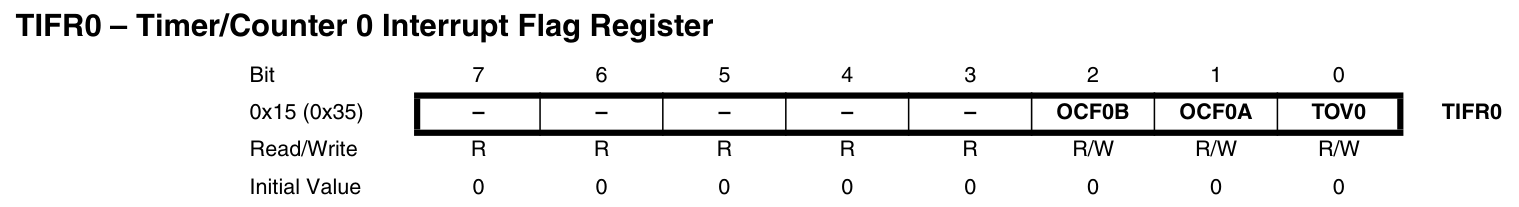
OCF0B :定时器0输出比较B匹配标志位,执行中断处理函数时自动清除,或者可以写 1 清除。OCF0A :定时器0输出比较A匹配标志位,执行中断处理函数时自动清除,或者可以写 1 清除。TOV0 :定时器0溢出标志位,执行中断处理函数时自动清除,或者可以写 1 清除。
控制LED闪烁周期
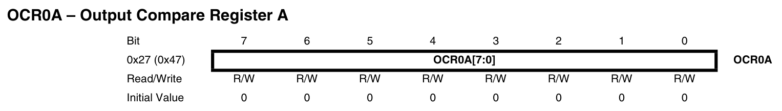
利用ATtiny88定时器0的CTC模式可以灵活控制LED的闪烁周期, OCR0A 寄存器的值可以通过下式计算得到:
\[OCR0A = time \times f_{T0} - 1 = time \times \frac{f_{IO}}{prescaler} - 1\]
代码文件的组织结构如下:
| .
├── Makefile
├── inc
└── src
└── main.c
|
其中 src/main.c 源文件的内容如下:
| src/main.c |
|---|
| #include <stdint.h>
#include <avr/io.h>
#include <avr/interrupt.h>
int main(void)
{
cli(); // disable global interrupt
DDRD |= _BV(DDD0); // set PD0 as output
PORTD |= _BV(PORTD0); // PD0 outputs high level
TCNT0 = 0; // clear counter
OCR0A = 249; // reload value, 1ms
TCCR0A = _BV(CTC0) | _BV(CS01) | _BV(CS00);
// CTC mode, prescaler = 64, clk_t0 = 250KHz
TIFR0 = _BV(OCF0A); // clear OCF0A flag
TIMSK0 = _BV(OCIE0A); // enable TIMER0_COMPA interrupt
sei(); // enable global interrupt
for (;;); // wait for interrupt
}
ISR(TIMER0_COMPA_vect)
{
static uint16_t count = 0;
uint8_t sreg = SREG; // store the status register
if (++count == 500) {
count = 0;
PIND = _BV(PIND0); // toggle PD0 every 500ms
}
SREG = sreg; // restore the status register
}
|
上述代码设置定时器0的时钟分频系数为64,即 \(f_{T0} = \frac{16MHz}{64} = 250KHz\) ;设置定时周期为1毫秒,即 \(OCR0A = 10^{-3}s \times 250KHz - 1 = 249\) ;同时,开启 TIMER0_COMPA 中断。在中断函数中,每500个周期翻转一次PD0的电平状态,实现了LED以1秒为周期的闪烁功能。
控制LED亮度
利用ATtiny88定时器0的普通模式,可以实现软件PWM功能,PWM的频率和占空比可以通过下式计算得到:
\[f_{PWM} = \frac{f_{T0}}{256} = \frac{f_{IO}}{prescaler \times 256}\]
\[duty = \frac{OCR0A + 1}{256}\]
代码文件的组织结构如下:
| .
├── Makefile
├── inc
└── src
└── main.c
|
其中 src\main.c 源文件的内容如下:
| src/main.c |
|---|
| #include <stdint.h>
#include <avr/io.h>
#include <avr/interrupt.h>
int main(void)
{
cli(); // disable global interrupt
DDRD |= _BV(DDD0); // set PD0 as output
PORTD &= ~_BV(PORTD0); // PD0 outputs low level
TCNT0 = 0; // clear counter
OCR0A = 0; // clear compare value
TCCR0A = _BV(CS01) | _BV(CS00); // normal mode, prescaler = 64, clk_t0 = 250KHz, f_pwm = 977Hz
TIFR0 = _BV(OCF0A) | _BV(TOV0); // clear OCF0A & TOV0 flag
TIMSK0 = _BV(OCIE0A) | _BV(TOIE0); // enable TIMER0_COMPA & TIMER0_OVF interrupt
sei(); // enable global interrupt
for (;;); // wait for interrupt
}
ISR(TIMER0_COMPA_vect)
{
uint8_t sreg = SREG; // store the status register
PORTD &= ~_BV(PORTD0); // PD0 outputs low level
SREG = sreg; // restore the status register
}
ISR(TIMER0_OVF_vect)
{
static uint8_t count = 0;
static int8_t inc = 1;
uint8_t sreg = SREG; // store the status register
PORTD |= _BV(PORTD0); // PD0 outputs high level
if (++count == 10) {
OCR0A += inc; // increase / decrease PWM duty every 10 cycles
if (OCR0A == 0xFF) {
inc = -1;
} else if (OCR0A == 0) {
inc = 1;
}
count = 0;
}
SREG = sreg; // restore the status register
}
|
上述代码设置定时器的时钟分频系数为64,则PWM的频率为 \(f_{PWM} = \frac{16MHz}{64 \times 256} \approx 977Hz\) ,并开启了 TIMER0_COMPA 和 TIMER0_OVF 中断。在 TIMER0_COMPA 中断里PD0输出低电平,在 TIMER0_OVF 中断里PD0输出高电平,另外每10个周期增加/减少一次占空比。
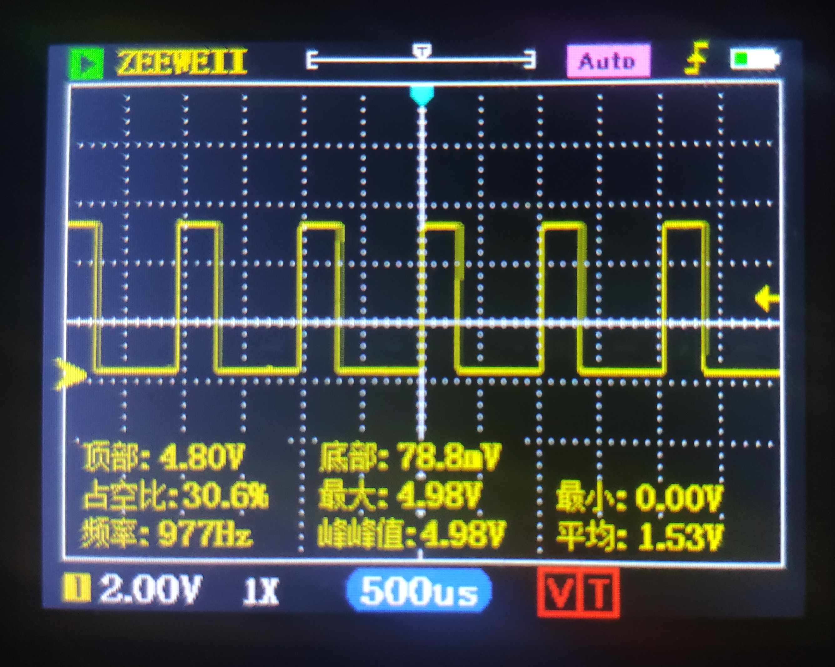
将代码下载到单片机后,板载LED将呈现呼吸灯的效果,由灭慢慢变亮,再由亮慢慢变灭。同时,将PD0引脚连接到示波器,可以看到频率为977Hz左右的PWM波,且占空比在规律变化,如下图所示:
注意:这种方法产生的PWM最低占空比为 \(\frac{1}{255}\) ,最高占空比介于 \(\frac{255}{256}\) 和1之间,这是因为虽然理论上 OCR0A 寄存器设置为255时占空比为1,但是在这种情况下 TIMER0_COMPA 和 TIMER0_OVF 这两个中断会同时产生,而 TIMER0_COMPA 中断的优先级比 TIMER0_OVF 高,因此会先执行 TIMER0_COMPA 中断,执行完后再执行 TIMER0_OVF 中断,所以PD0会输出一个时间很短的低电平脉冲,导致实际占空比达不到1。
参考资料
- ATtiny88 Datasheet
- Programming and Interfacing ATMEL's AVRs